
 English

Installation Decides Pump Life Before the First Start
A correctly specified chemical pump can still fail in its first month of service, and in most of those cases the pump itself is not at fault. Field experience across the process industries points the same way: the leading causes of premature bearing, seal, and coupling failure are installation defects. A twisted baseplate, piping forced onto the nozzles, or a coupling aligned once at the factory and never checked again will destroy a precision machine that left the workshop in perfect condition. This guide covers the three areas that decide installation quality: foundation and grouting, piping loads, and shaft alignment, with the acceptance values and field checks that separate a durable installation from a future failure.
Foundation and Baseplate
The Concrete Foundation
The foundation has four jobs: provide a flat reference surface, hold the equipment under starting and operating loads, absorb vibration, and give maintenance a repeatable position to work from. Use a rigid, level concrete base with enough mass to damp vibration. Before setting the baseplate, inspect the pad for settlement, cracks, oil contamination, and standing chemical residue. A practical field target for foundation flatness is 0.1 mm per meter, checked with a precision level in more than one direction: along the base, across it, and diagonally on long frames. A single reading along the motor axis is not enough, because a base can read level end-to-end and still be twisted.
Leveling, Shims, and Grouting
Level the baseplate on steel shims or wedges placed beside each anchor bolt, rough-align the pump and motor, and only then grout. Use non-shrink grout, pour it continuously to avoid cold joints, and fill the baseplate completely. Hollow voids under the baseplate act as vibration amplifiers and eventually crack. Allow the grout to cure per the manufacturer's instructions, typically 24 to 48 hours, before final bolt torquing and final alignment. Tighten anchor bolts in a balanced cross pattern to the specified torque; the goal is even contact, not maximum force on the nearest bolt. One discipline worth enforcing: place shims under the motor feet, never under the pump feet. Motor-side shimming leaves room for future alignment correction without disturbing the piping that is already fitted to the pump nozzles.
Piping: The Pump Carries No Pipe Weight
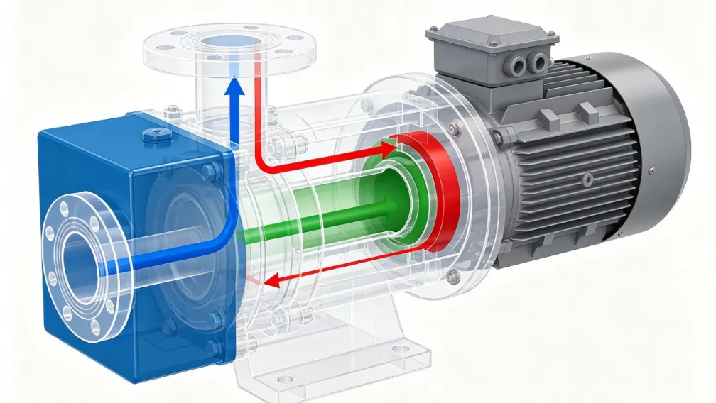
Pipe strain is the single most common installation defect on chemical pumps, and the most damaging. A casing pulled out of shape by piping loads distorts the seal chamber, shifts the shaft, and can crack a fluoroplastic lining at the flange. The rule is absolute: pipe flanges must meet the pump nozzles naturally, without springing, forcing, or drawing them into position with bolts.
Independent Supports and the Flange Check
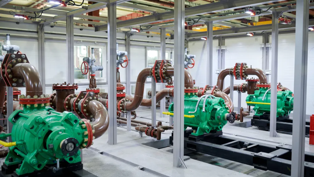
Support suction and discharge piping independently near the pump, so the pump carries none of the pipe weight, including the weight of the liquid inside it. There is a simple field verification. With the line isolated and drained, loosen the nearest flange. The pipe should stay in position. If it moves vertically, sideways, or rotates to reach the nozzle, the pipe was loading the pump and the supports or routing need correction. Never close a misaligned flange with bolt force; on lined piping the lining turnout on the flange face is the sealing surface, and over-tightening a sprung joint crushes it into a future leak path.
Suction Piping Design
Most hydraulic complaints trace back to the suction line. Keep it short and direct, run it continuously rising toward the pump so no air pockets can form, and provide a straight run of 5 to 10 pipe diameters between the suction nozzle and the first elbow or obstruction to give the impeller a uniform flow field. Where a reducer is needed, use an eccentric reducer installed flat on top; a concentric reducer traps air at the crown of the line. Size the line to keep velocity low, and never throttle flow on the suction side. Regulation belongs on the discharge valve; a throttled suction starves the pump, drops the inlet pressure below the fluid's vapor pressure, and produces cavitation that sounds like gravel and erodes impellers.
Thermal Expansion
Chemical piping moves with temperature, and plastic-lined piping moves more than steel. Provide for that movement with sliding supports, loops, or expansion joints. Do not place rigid three-dimensional anchors near the pump nozzles: an anchored line that heats up has nowhere to grow except into the pump, and the resulting nozzle loads can reach thousands of kilograms on a modest line size. Flexible connectors are for absorbing controlled movement and vibration, not for bridging misalignment; a connector that is already stretched or twisted at ambient temperature has nothing left when the line warms up.
Matching Lined Components
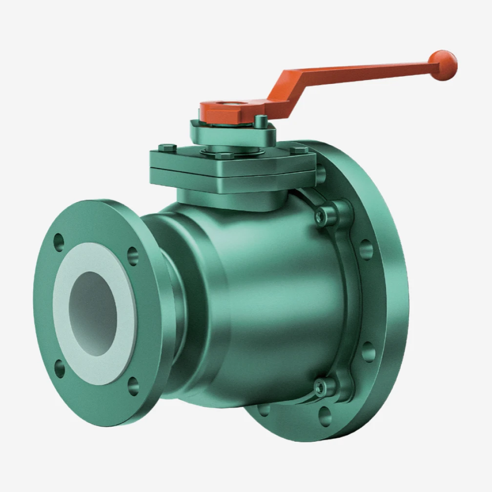
On lined systems, keep flange standards consistent end to end. Use matched fluoroplastic-lined valves, pipes, and fittings rated to the same standard as the pump nozzles (PN10/PN16 or ANSI 150) so flange faces, bolt patterns, and lining turnouts align. Mixing standards forces adapters and creates the misalignment that this section exists to prevent.
Shaft Alignment
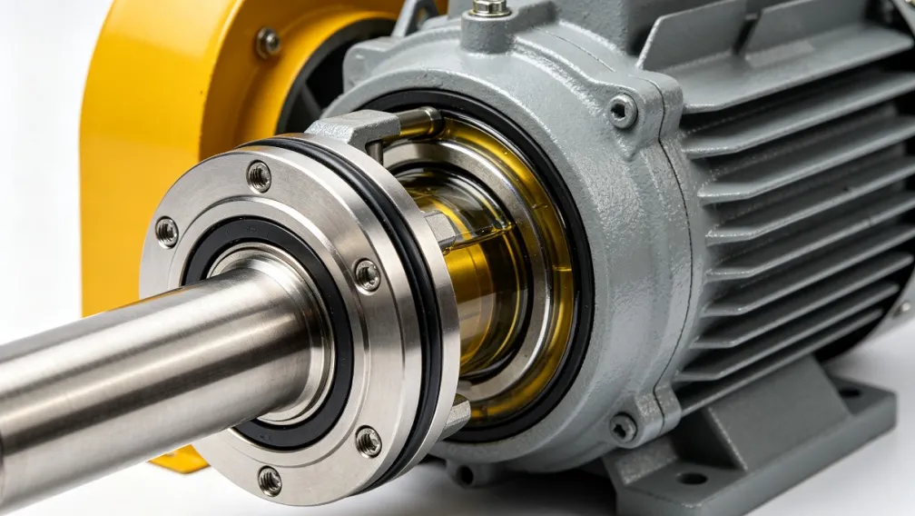
Misalignment is the leading mechanical cause of premature bearing and mechanical seal failure, and on a magnetic drive pump it additionally loads the coupling magnets and shortens sleeve bearing life. Factory alignment does not survive transport, baseplate work, and piping connection, so alignment is a site activity, not a certificate.
Method and Target
Use a dial indicator or laser alignment system and measure parallel and angular offset. A practical target for general chemical duty is 0.05 mm total indicated reading; high-speed or critical service may demand tighter values from the pump manual, and those override any general figure. A straightedge is acceptable as a quick screen, never as the final acceptance record on a corrosive-duty pump.
The Alignment Sequence
Alignment holds only when it is verified in sequence:
- Rough alignment before grouting, to establish the geometry.
- Re-check after the grout cures and anchor bolts are torqued, because grouting moves things.
- Final alignment after suction and discharge piping is connected, supported, and filled. A pump aligned before piping and never re-checked has not been aligned at all.
- Hot alignment on pumps running warm. Thermal growth lifts and shifts both casings and motors, so for fluid temperatures above roughly 90°C, verify alignment at operating temperature during the first planned shutdown.
Rotation Check
Before coupling the motor, bump it briefly with the coupling element removed and confirm rotation against the arrow on the casing. Reverse rotation delivers little flow, and on pumps with threaded impeller components it can unscrew the impeller nut within seconds. This check costs ten seconds and prevents one of the few failures that can destroy a new pump on its first start.
Chemical-Service Installation Specifics
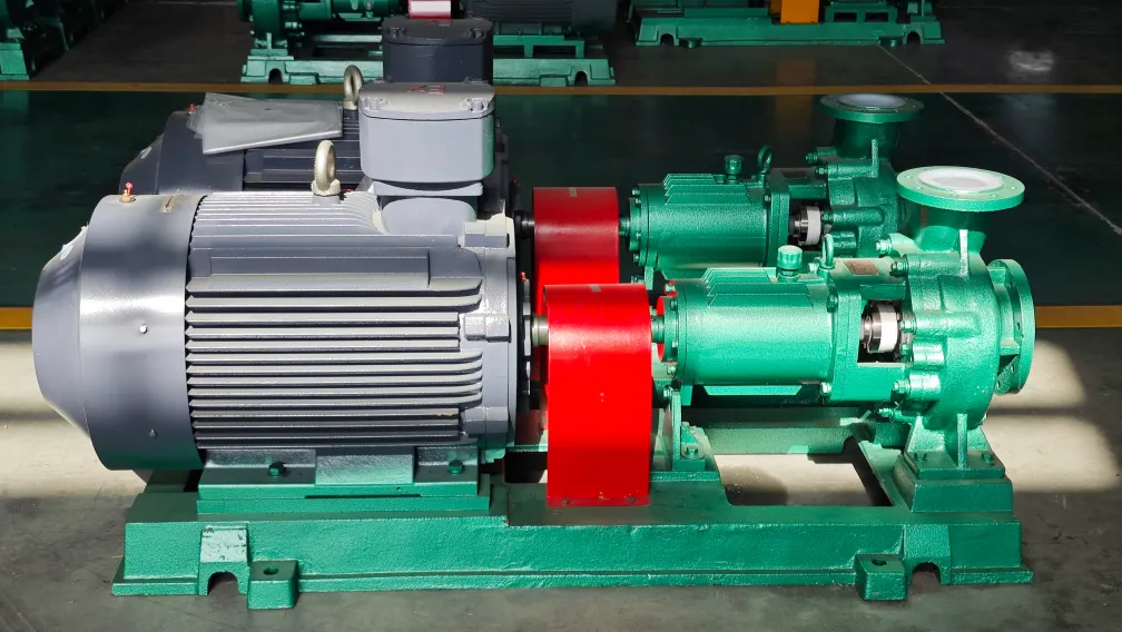
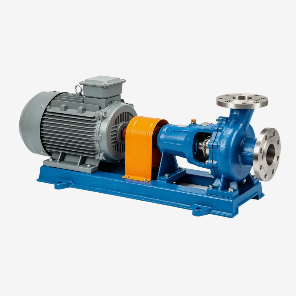
Corrosive duty adds requirements beyond the standard mechanical checklist. Provide a containment tray or curbed area under the pump with drainage to a neutralization point, sized for a seal failure, so a leak is a maintenance event instead of an environmental one. Route seal flush and barrier fluid lines with instruments visible from the operating position. Leave service access: a technician must be able to remove the coupling guard, reach drain and vent plugs, and use a torque wrench without standing on pipework. On back pull-out designs, confirm clearance behind the pump to withdraw the motor and bracket without disturbing the casing or piping, which is what makes the design worth specifying in the first place. Keep welding and flame work away from lined equipment; local heat destroys a fluoroplastic lining from the inside before any damage shows outside.
Installation Acceptance Checklist
Before introducing process liquid, record the following. The record is the baseline every later vibration or leakage investigation will be compared against.
| Item | Acceptance criterion |
|---|---|
| Foundation flatness | Within 0.1 mm/m in multiple directions, no settlement or contamination |
| Grouting | Non-shrink grout, full contact without voids, cured 24 to 48 hours |
| Anchor bolts | Correct torque, balanced pattern, witness marks applied |
| Pipe supports | Independent near pump; loosened flange shows no pipe movement |
| Suction line | Short, rising, 5 to 10 diameters straight run, eccentric reducer flat on top |
| Alignment | Within 0.05 mm or manual limit, measured after piping is connected and filled |
| Rotation | Confirmed with coupling disconnected, matches casing arrow |
| Auxiliaries | Flush and barrier lines flowing at correct pressure, instruments readable |
| Containment and access | Tray drained to neutralization; guard, plugs, and pull-out space clear |
Conclusion
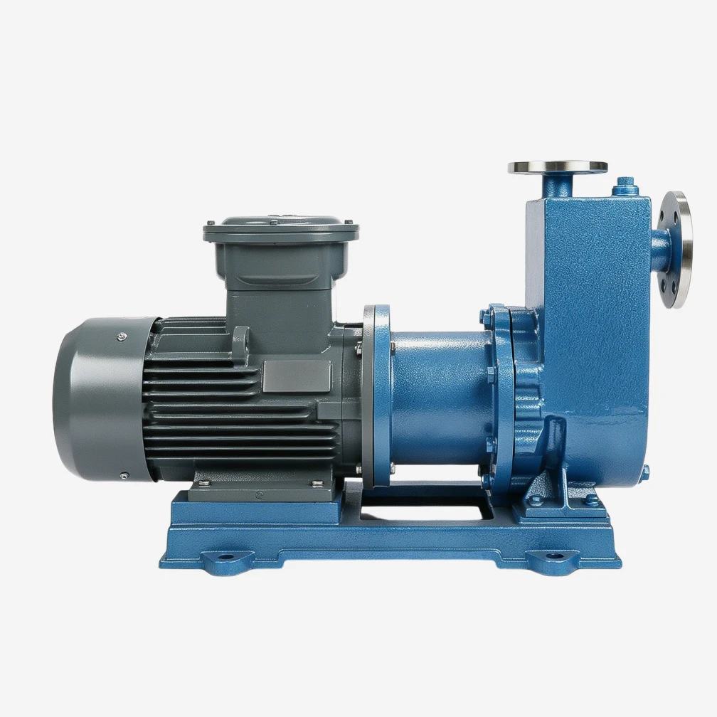
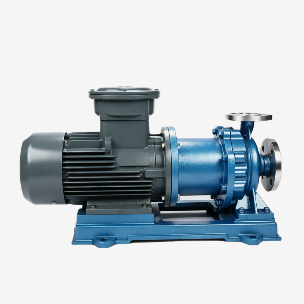
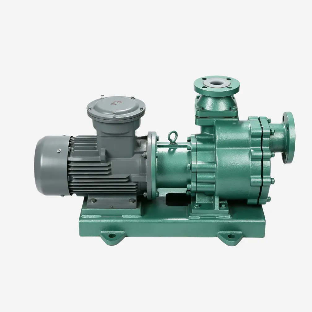
Pump reliability is built on the ground, literally. A flat foundation, fully grouted baseplate, piping that stands on its own supports, and alignment verified after the piping is connected will deliver the service life the pump was engineered for, whether it is a lined centrifugal chemical pump or a sealless magnetic drive unit. Skipping any one of these steps converts a capital asset into a maintenance problem within months. YFTEL supplies installation drawings, nozzle load limits, and commissioning support with every pump. Send us your foundation and piping layout at the project stage, and our engineers will flag the risks before the concrete is poured.
-

YFTEL Pumps
Fluid Engineers & Technical Support, YFTEL Pump
YFTEL is a chemical pump manufacturer based in Hangzhou, China, with a 26,000 m² production base in Hangzhou, China, with a 26,000 m² production base in Anhui. Using the CAS-patented Fluoroplastic Alloy material, we produce 300+ models of corrosion-resistant pumps, valves and piping, exported to 30+ countries.